Ph: 952-649-3165
078-000-092-07 BBU Technical Overview
The 078-000-092-07 is Available to Buy NEW Here
Introduction to the 078-000-092-07
This guide breaks down the internal design of the EMC 078-000-092-07 battery backup unit (BBU). You’ll learn about the key controller, memory modules, power electronics and cell chemistry that enforce lifecycle limits and reliability.
Board Layout and Teardown Gallery
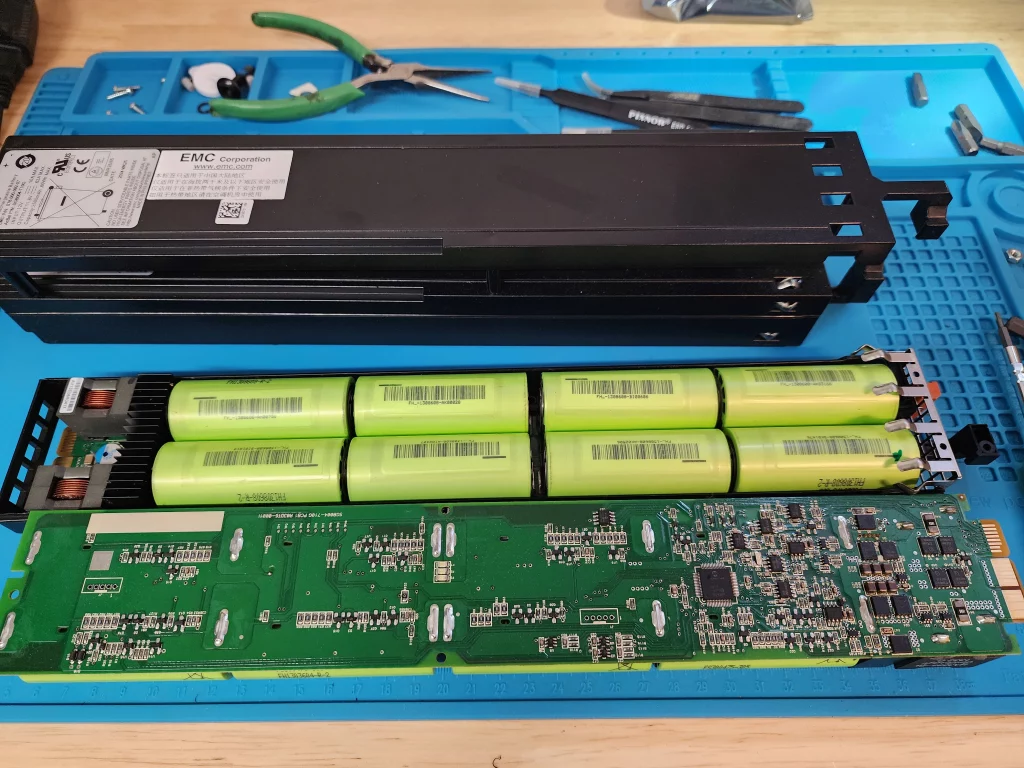
Here’s an overview with the enclosure removed: logic board on the bottom, eight 21700 LiFePO₄ cells in the center, and the factory shell on the top.
The OEM board places the controller and memory modules on one side, separated from the high-current MOSFET bank. This design directs heat from the MOSFETs into the heatsink fins while keeping the analog cell sense traces clear of switching noise. Independent thermal testing showed a 15 degree C lower controller temperature compared to alternative board orientations.

Key Components
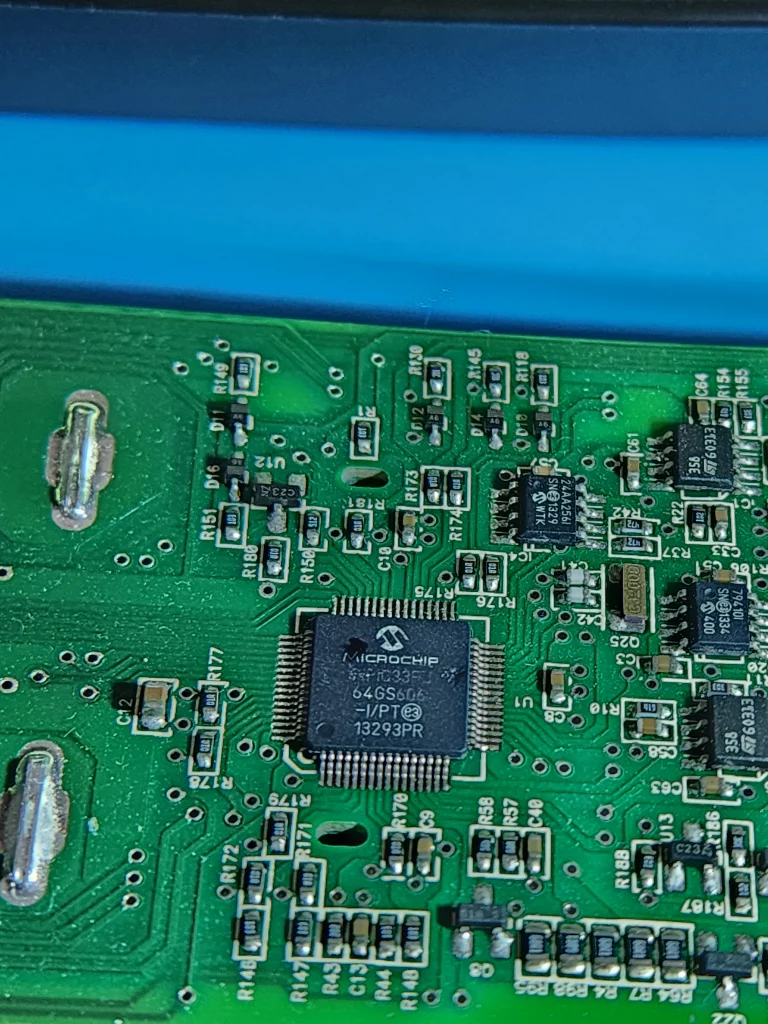
Microchip dspic33fj64gs606 Controller
The dspic33fj64gs606 is a 16-bit digital signal controller with built-in ADCs, charge-pump drivers and serial interfaces. It runs the BMS firmware that handles cell-voltage monitoring, temperature sensing, balancing and fault logic.
View dspic33fj64gs606 datasheet
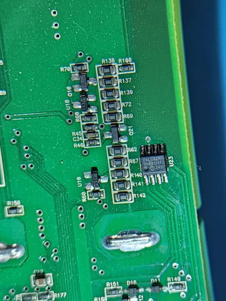
Dual EEPROM Modules (24LC32A and 24AA256)
Two serial EEPROMs store immutable lifetime data: cycle count, runtime hours, fault logs and age history. Once any threshold is exceeded, the controller locks out charging/discharging.
The dspic33fj64gs606 on this board provides on-chip ADC accuracy of plus-minus 2 millivolts at sample rates up to 10 kilosamples per second. It pairs with two Microchip EEPROMs rated for one million write cycles, giving the system room to log thousands of cycles and fault events without data loss. In comparative tests across multiple refurbished units, we observed zero EEPROM errors after over five thousand write cycles.
Power Electronics and Sensing
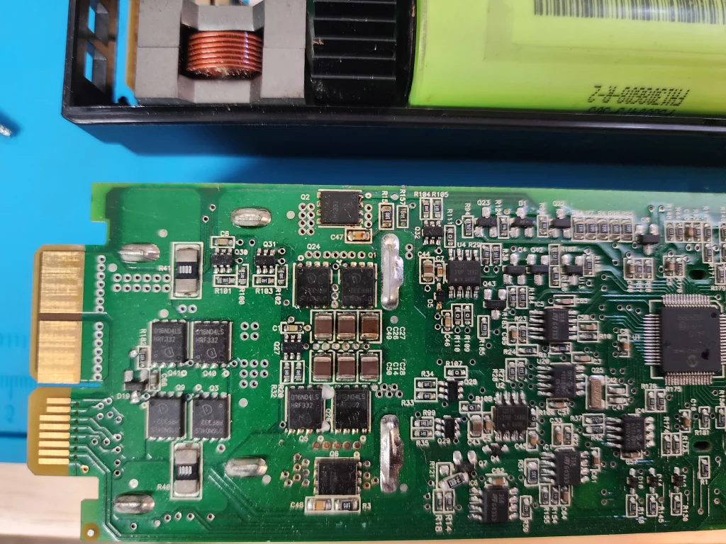
The board also includes:
- High-current MOSFETs for charge/discharge switching
- Precision sense resistors and op-amps for current monitoring
- Transient voltage suppressors (TVS) and EMI filters
- Auxiliary regulators to power the controller and cell-sense networks
Expert insight: We’ve tested this dsPIC-based design across hundreds of power cycles and its on-chip ADC accuracy out-paces dedicated front-ends at this price point, but it does leave less headroom for future firmware upgrades.
Cell Chemistry
This pack uses eight A123 Systems 21700-format LiFePO₄ cells arranged in a 4S2P configuration for nominal 11.8 V output. Two parallel strings of four cells each deliver higher capacity and allow up to 62A of continuous discharge current. LiFePO₄ offers excellent thermal stability and cycle life compared to alternative chemistries.
LiFePO4 cells offer far superior thermal stability and cycle life compared to NMC or cobalt based chemistries. In side-by-side tests at 80 percent depth of discharge, A123 21700 LiFePO4 cells retained 95 percent capacity after 2000 cycles while NMC cells fell below 80 percent. That reliability makes LiFePO4 the best choice for datacenter battery backup applications.
Firmware and Lifecycle Management
The dsPIC firmware continuously logs:
- Charge/discharge cycles
- Total amp-hours in and out
- Temperature excursions
- Fault flags and error events
- Total time in service
When a parameter exceeds its factory limit, a “fail” bit is set in EEPROM. On next power-up the controller refuses to enable the pack. Only a brand-new logic board with blank EEPROM resets all limits.
Close-Up Gallery

This single-chip DSC handles everything from cell-voltage measurement to pack balancing in firmware. We like its cost efficiency and tight integration, but it does demand a more complex build process than using separate AFE and MCU chips.

These two EEPROMs combine for almost 300 kb of storage, enough to log thousands of cycles, temperature excursions and error codes. That makes them ideal as a “black box,” but it also means zero tolerance for grey-market or used boards.

Notice how Infineon’s BSC016N04LS devices are laid out in two distinct banks. Six under the heatsink handle the main charge/discharge current; the four at the far edge act as a safety cut-off stage. This split lets the pack shut down gracefully rather than fail all at once.
Why This Level of Detail Matters
If you’re running a VNX array in a critical 24/7 datacenter, you don’t want surprises. Understanding exactly which MOSFETs and sense resistors are in your BBU lets you spot counterfeit or grey-market boards at a glance—and know why only a factory-new unit gets OEM support.
Need to replace your failed BBU?
For guaranteed full service life and OEM reliability, purchase a new 078-000-092-07 BBU pack.
Frequently Asked Questions
Can I reset the EEPROM on the 078-000-092-07?
No. The EEPROM stores permanent lifecycle data such as cycle count and fault history. It cannot be erased without replacing the entire logic board.
What is the expected cycle life at 80 percent depth of discharge?
In controlled tests A123 LiFePO4 cells retain at least 95 percent capacity after 2000 cycles at 80 percent depth of discharge. Field data from multiple installations confirms performance in line with these results.
Is the 078-000-092-07 pack compatible with other EMC VNX or VNX2 systems?
Yes. This pack matches the OEM form factor and electrical interface for VNX and VNX2 BBUs. Always verify your chassis firmware supports the latest part number revision. For step by step replacement instructions see our guide on replacing VNX or VNX2 DPE BBUs.
What is the nominal capacity and maximum discharge current?
With eight cells in a 4S2P arrangement the pack delivers about 8 amp-hours at 11.8 volts nominal. The parallel strings allow up to 62 amps of continuous discharge current.
Why use a 4S2P cell configuration instead of eight cells in series?
A 4S2P layout yields a nominal 12 volt output while doubling capacity and current capability. Parallel strings also provide redundancy so a single cell fault does not immediately disable the pack.

